/*
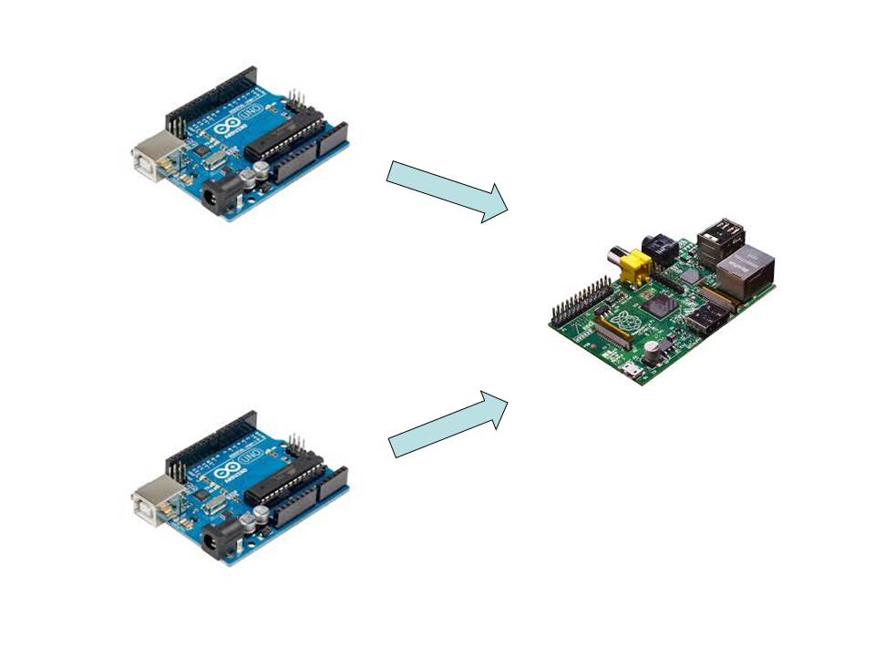
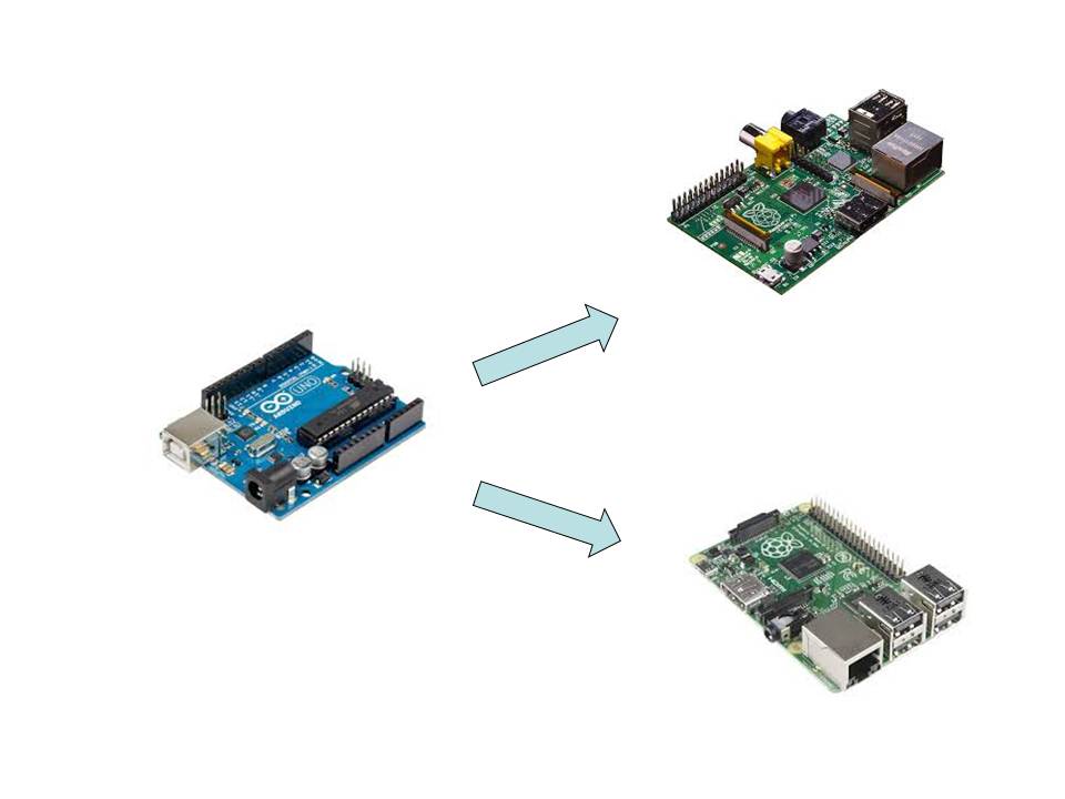
* nRF24L01 Sample Program (Send to 2 Server)
*
* VCC 3.3V
* MISO 12
* MOSI 11
* SCK 13
* CE 7
* CSN 8
*/
#include <SPI.h>
#include "RF24.h"
/* Hardware configuration: Set up nRF24L01 radio on SPI
bus plus pins 7 & 8 */
RF24 radio(7,8);
// Radio pipe addresses for the 2 nodes to communicate.
byte addresses[][6] = {"1Node","2Node","3Node"};
void setup(void)
{
Serial.begin(115200);
radio.begin();
// Set the PA Level low to prevent power supply
related issues since this is a
// getting_started sketch, and the likelihood of
close proximity of the devices. RF24_PA_MAX is default.
radio.setPALevel(RF24_PA_LOW);
// Open a writing and reading pipe on each radio,
with opposite addresses
//radio.openWritingPipe(addresses[1]);
//radio.openReadingPipe(1,addresses[0]);
// Start the radio listening for data
radio.startListening();
}
void radio_send(unsigned long put_time) {
// First, stop listening so we can talk.
radio.stopListening();
Serial.println(F("Now sending"));
// Take the time, and send it. This will
block until complete
unsigned long start_time = micros();
if (!radio.write( &put_time, sizeof(unsigned
long) )){
Serial.println(F("failed"));
}
radio.startListening();
// Now, continue listening
unsigned long started_waiting_at =
micros(); // Set up a timeout period,
get the current microseconds
boolean timeout =
false;
// Set up a variable to indicate if a response was
received or not
while ( ! radio.available()
){
// While nothing is received
if (micros() - started_waiting_at >
200000 ){ // If waited longer than 200ms, indicate timeout
and exit while loop
timeout = true;
break;
}
}
if ( timeout
){
// Describe the results
Serial.println(F("Failed, response
timed out."));
}else{
unsigned long
got_time;
// Grab the response, compare, and send to debugging spew
radio.read( &got_time,
sizeof(unsigned long) );
unsigned long end_time = micros();
// Spew it
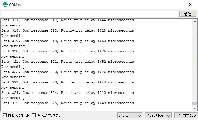
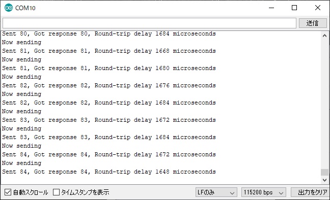
Serial.print(F("Sent "));
Serial.print(put_time);
Serial.print(F(", Got response "));
Serial.print(got_time);
Serial.print(F(", Round-trip delay "));
Serial.print(end_time-start_time);
Serial.println(F(" microseconds"));
}
}
void loop(void)
{
static unsigned long put_time = 0;
// Open a writing and reading pipe on each radio,
with opposite addresses
if ((put_time % 2) == 0) {
radio.openWritingPipe(addresses[1]);
radio.openReadingPipe(1,addresses[0]);
} else {
radio.openWritingPipe(addresses[2]);
radio.openReadingPipe(1,addresses[0]);
}
radio_send(put_time);
put_time++;
// Try again 1s later
delay(1000);
}
|